In Part 1 and Part 2 we built Openwrt for the GL-iNet and configured it to bypass 802.1x port security. Now I will discuss adding hardware to the device to enable HID based attacks. A Teensy will be added to the GL-iNet with interaction via General Purpose Input/Output (GPIO) to enable/execute commands.
There are several hardware and software projects for weaponizing the Teensy. Links to those projects can be found at the bottom of this document. The Teensy is a USB-based microcontroller development system that can be used to mimic a human interface device (HID) (keyboard or mouse). The goal is to have the ability to remotely activate code stored on the Teensy. The stored code will execute against the workstation as keystrokes, mouse movements and mouse clicks. The activation comes from the GPIOs on the GL-iNet connected to the Teensy. The pins on the Teensy are all pulled-down via 10K ohm resistors reading near zero voltage. Code on the Teensy will wait for one of the pins to “go High” which occurs when a GPIO is turned on sending a signal to the corresponding Teensy pin.
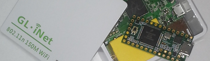
This quick tutorial details how to add a Teensy 2.0 to the GL-iNet. The Teensy will be powered by the internal GL-iNet 5v header with the USB Data -/+ wired to the GL-iNet USB power header. Why the Teensy 2.0? Because I had a handful on hand that I wanted to use.
Remove Teensy Mini USB Header (optional)
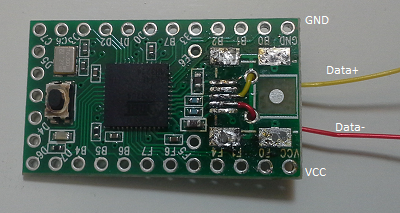
Since we will be wiring the Teensy to the GL-iNet we will not need the Mini-USB header. Carefully de-solder the header from the Teensy. Solder three wires to the Teensy connected at VCC, Data +, and Data -. You will not need to solder a wire for ground (GND).
Connect Teensy to the GL-iNet
The GPIO header on the GL-iNet is not the same size as the pinout on the Teensy. The GL-iNet GPIO headers are 2mm pitch while the Teensy uses the more common 2.54mm pitch. Since they don’t line up the Teensy will not fit as nice in the GL-iNet. You will have to wire the connections.
What I did was take a couple breadboard jumper wires and twist them to rig it so the Teensy was “mounted” in the GL-iNet.

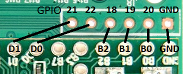
Based on the positioning of the modified jumper wires my Teensy matched up with the GL-iNet as shown in Figure 3.
Add 10K Ohm Resistors
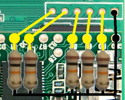
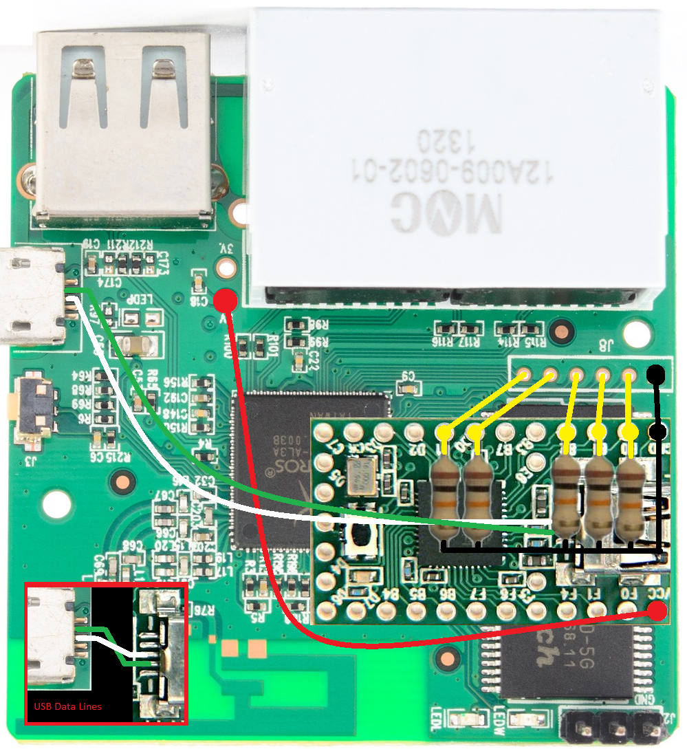
Once the Teensy is soldered and “mounted” to the GL-iNet you will need to pull the pins to ground so that they will always initially read with a near zero voltage. See the references section at the bottom to learn more about pull-up and pull-down resistors and why they are used. You probably could get fancy with some smaller resistors but I only had the garden variety.
Connect USB Data Lines and USB Power
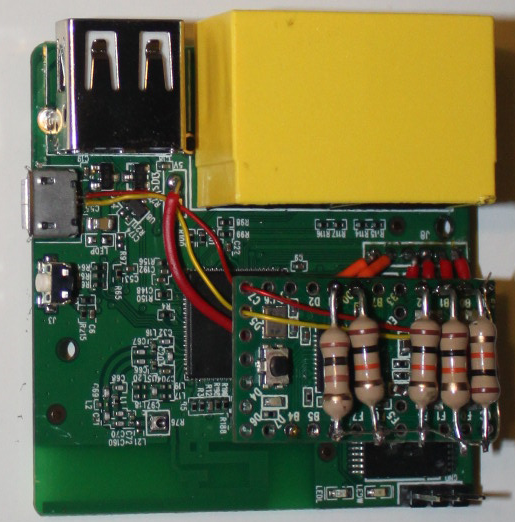
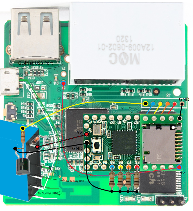
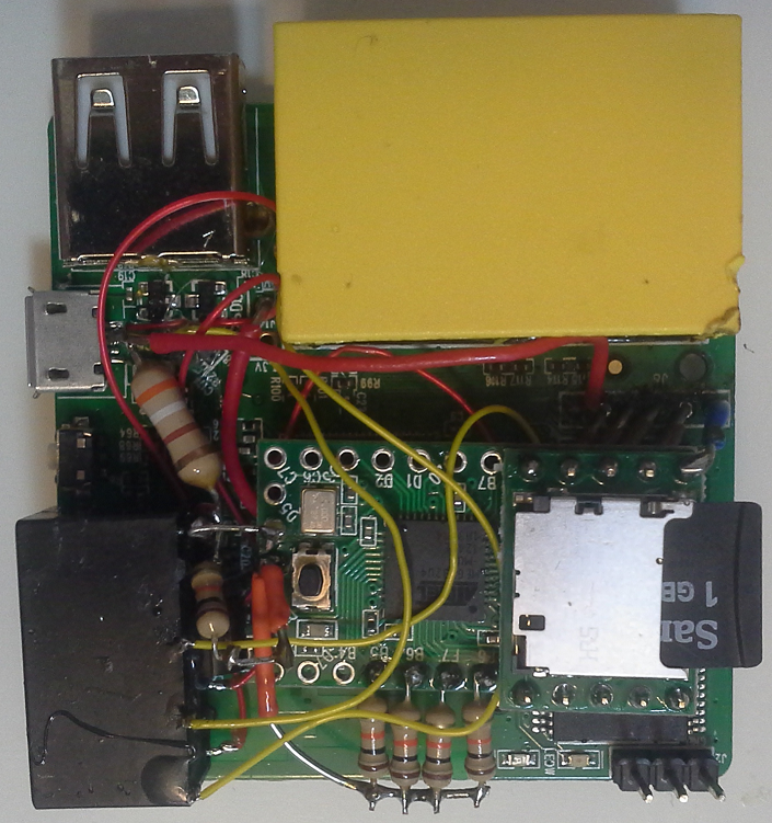
Wire the VCC pin on the Teensy to the 5v pin on the GL-iNet. Then wire the Data- and Data+ lines on Teensy to the USB port of the GL-iNet. See Figure 5 for a mockup of the wiring Figure 6 for an image of what the beast looks like. NOTE: I had a newer version of the GL-iNet (model 6416A) and the 5V and 3V pins on the header were reversed compared to the picture found on openwrt.org.
Setup Issues
This setup works great but there is one major issue. The Teensy 2.0 has a very limited amount of storage space and RAM to store and execute code. This severely limits what this project aims to accomplish. I used a Teensy 2.0 because I had a handful of them lying around and finally got around to using them. Too bad the Teensy 3.1 is out with over 8x the flash memory and over 25x the RAM! There was no chance in hell the awesome code put together by Mike Czumak (see reference below) was going to be able to work with this setup.
So I did two things:
• I ordered a couple Teensy 3.1 devices and another GL-iNet (look for Part 3.1 in the future).
• I realized I had an SD Card adaptor for the Teensy 2.0 so I went back to the drawing board for the current iteration of this project.
GL-iTeen v 0.2 (working title)
The addition of the SD Card adaptor to the Teensy 2.0 allows for a multitude of options for attack and penetration testing which will be detailed in Part 5 of this tutorial. Version 0.1 of the device had to be dismantled due to flash and RAM size limitations. An SD Card Adapter will be installed to help alleviate some of the storage limitations. Adding the SD Card also had the unintended effect of adding additional attack vectors!
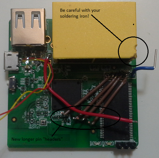
Installation of the SD Card adapter will take up three of the pins on the Teensy that were connected to the GL-iNet GPIO. All wiring was removed and longer “header” pins were put in to reach the Teensy pins on the other side (Figure 7) The connection to the Teensy will be at pins B5, B6, F6, & F7 (Figure 8).

I mentioned the addition of the SD Card led to a new attack vector. The ability to download files from the Teensy, run them, and upload the results. When the device is retrieved you can then access the data collected. But what if you wanted to view those files on the GL-iNet during the attack? Could you switch the Teensy USB connection from that host you are attacking to the USB on the GL-iNet? Could you control this via GPIO? The answers are yes, yes, and yes!
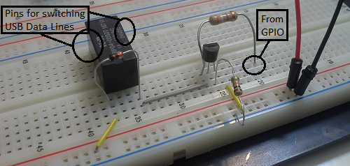
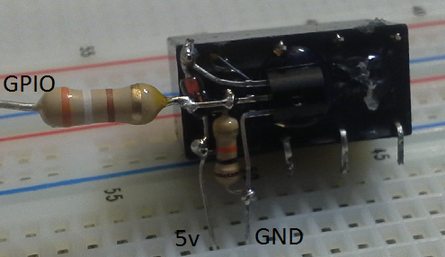
I’m still very much a novice in the realm of electronics (I’m currently working through Make: Electronics by Charles Platt) so if there is a better way to do these please reach out to me. All of the parts I had on hand to implement this. The most important part is it works! I control the switching of the USB data lines via a relay. A 5v relay is controlled via a transistor connected to one of the GPIO pins. Turning the GPIO to “on” activates the transistor allowing the flow of current through the relay which switches the data connection. I got the switching configuration from a SparkFun Tutorial. See the link in the reference sectioned at the end. Figure 9 is the schematic from the tutorial where I cross out the sections that are not pertinent to my project. Also note that in the schematic a 1K ohm resistor is used from the GPIO pin and I actually use a 380 ohm resistor.
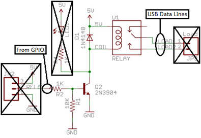
Figure 10 shows the setup on a breadboard. Connecting a voltage to simulate the activation of a GPIO should illicit a clicking sound from the relay. Figure 11 shows how we will fit this in the GL-iNet.
The final two figures show a mock-up of how everything is connected and how it looks ready for prime time. Part 4 will detail code to test that this all works. Part 5 will detail the attack code we use on the Teensy and the files and programs we include on the SD Card.
References
What is GPIO
http://en.wikipedia.org/wiki/General-purpose_input/output
http://wiki.openwrt.org/doc/hardware/port.gpio
Pull-up and Pull-down Resistors
http://playground.arduino.cc/CommonTopics/PullUpDownResistor
Programmable HID USB Keystroke Dongle by Adrian “Irongeek” Crenshaw
http://www.irongeek.com/i.php?page=security/programmable-hid-usb-keystroke-dongle
Fun with Teensy by Mike Czumak
http://www.securitysift.com/fun-with-teensy/
Advanced Teensy Penetration Testing
https://www.offensive-security.com/offsec/advanced-teensy-penetration-testing-payloads/
SparkFun Tutorial: Controllable Power Outlet
https://www.sparkfun.com/tutorials/119