Part 4 – Remote HID Attacks with a Teensy – Testing Your Build / Getting Started
GL-iNet GPIO Setup
Pins 18,19,20,21,22 are available as GPIOs for the GL-iNet. The script below will activate the GPIOs and set them to “low”. GPIO 21 is responsible for the Teensy 2.0 USB communication. GPIOs 18, 19, 20, & 22 provide the option to execute Teensy HID commands and will be discussed below. From the GL-iNet command prompt we can download the code below.
#!/bin/sh /etc/rc.common
#set GPIO
START=10
start() {

  echo 18 > /sys/class/gpio/export
  echo out > /sys/class/gpio/gpio18/direction
  echo 0 > /sys/devices/virtual/gpio/gpio18/value

  echo 19 > /sys/class/gpio/export
  echo out > /sys/class/gpio/gpio19/direction
  echo 0 > /sys/devices/virtual/gpio/gpio19/value

  echo 20 > /sys/class/gpio/export
  echo out > /sys/class/gpio/gpio20/direction
  echo 0 > /sys/devices/virtual/gpio/gpio20/value

  echo 21 > /sys/class/gpio/export
  echo out > /sys/class/gpio/gpio21/direction
  echo 0 > /sys/devices/virtual/gpio/gpio21/value

  echo 22 > /sys/class/gpio/export
  echo out > /sys/class/gpio/gpio22/direction
  echo 0 > /sys/devices/virtual/gpio/gpio22/value
}
root@OpenWrt:/# cd /etc/init.d
root@OpenWrt:/etc/init.d# wget http://www.jedge.com/code/setgpio
root@OpenWrt:/etc/init.d# chmod 755 setgpio
root@OpenWrt:/etc/init.d# /etc/init.d/setgpio enableFirst things first, how do we know what we built in Part 3 ( or 3.1) actually works? The first round of code for the Teensy will allow is to test it to ensure all that soldering actually connected your knee bone to your thigh bone. Our test code will ensure that we can access the SD card and that activation of the GPIOs from the GL-iNet are seen by the Teensy.
The Software
I’m not going to go into too much detail on getting your environment setup and configured to work with the Teensy. Excellent tutorials exist on downloading and installing the Arduino and Teensy software for your platform of choice. I will be using the following on a Windows 7 system:
Teensyduino – https://www.pjrc.com/teensy/teensyduino.html
Teensy Loader – https://www.pjrc.com/teensy/loader.html
Format the SD Card
Ensure your SD Card is properly formatted. Use the formatter tool from sdcard.org to properly format your card for best read/write performance for use with the Teensy. For this tutorial my SD Card is called SDCARD.
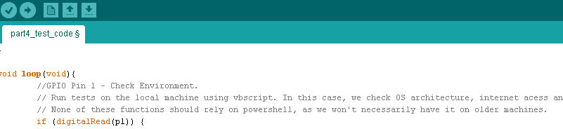
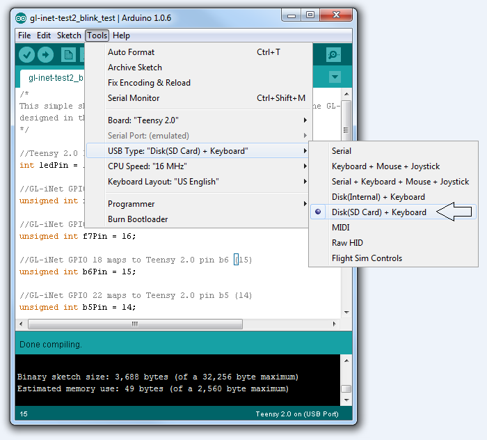
Teensy 2.0 Test Sketch
Go here for the sketch file. Before we compile and install the code ensure you have Disk(SD Card) + Keyboard selected (Figure 1).
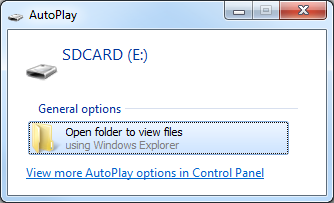
When you compile and install the code, if your Teensy is set to automatically reboot, you should be prompted with an Autoplay window (Figure 2).
Connect to your GL-iNet
Access a shell on your GL-iNet, either from the serial port or SSH, and run the setgpio shell script from Part 2. Ensure you are able to see the LED on your Teensy. Activation of the GPIOs will cause the LED to blink 1-4 times based on which GPIO is activated. In this example we will activate GPIO 19 which should cause the LED to blink twice every 4 seconds.
root@OpenWrt:~# echo 1 > /sys/devices/virtual/gpio/gpio19/value
root@OpenWrt:~# echo 0 > /sys/devices/virtual/gpio/gpio19/value
Test the Relay Switch
Now we will activate GPIO 21 which should switch the relay and connect the Teensy USB connection from the workstation to the GL-iNet. If you are connected through the serial port you will immediately see the success of the drive being recognized.
root@OpenWrt:~# echo 1 > /sys/devices/virtual/gpio/gpio21/value
root@OpenWrt:~# [17231.710000] usb 1-1: new full-speed USB device number 3 using ehci-platform
[17231.870000] scsi0 : usb-storage 1-1:1.0
[17232.870000] scsi 0:0:0:0: Direct-Access     Generic  USB Flash Disc   1.00 PQ: 0 ANSI: 4
[17232.890000] sd 0:0:0:0: [sda] 1984000 512-byte logical blocks: (1.01 GB/968 MiB)
[17232.890000] sd 0:0:0:0: [sda] Write Protect is off
[17232.900000] sd 0:0:0:0: [sda] No Caching mode page present
[17232.910000] sd 0:0:0:0: [sda] Assuming drive cache: write through
[17232.930000] sd 0:0:0:0: [sda] No Caching mode page present
[17232.940000] sd 0:0:0:0: [sda] Assuming drive cache: write through
[17232.950000]  sda: sda1
[17232.970000] sd 0:0:0:0: [sda] No Caching mode page present
[17232.970000] sd 0:0:0:0: [sda] Assuming drive cache: write through
[17232.980000] sd 0:0:0:0: [sda] Attached SCSI removable disk
root@OpenWrt:~# dmesg |tail -n 15
[17200.550000] usbcore: registered new interface driver ums-usbat
[17231.710000] usb 1-1: new full-speed USB device number 3 using ehci-platform
[17231.870000] scsi0 : usb-storage 1-1:1.0
[17232.870000] scsi 0:0:0:0: Direct-Access     Generic  USB Flash Disc   1.00 PQ: 0 ANSI: 4
[17232.890000] sd 0:0:0:0: [sda] 1984000 512-byte logical blocks: (1.01 GB/968 MiB)
[17232.890000] sd 0:0:0:0: [sda] Write Protect is off
[17232.900000] sd 0:0:0:0: [sda] Mode Sense: 03 00 00 00
[17232.900000] sd 0:0:0:0: [sda] No Caching mode page present
[17232.910000] sd 0:0:0:0: [sda] Assuming drive cache: write through
[17232.930000] sd 0:0:0:0: [sda] No Caching mode page present
[17232.940000] sd 0:0:0:0: [sda] Assuming drive cache: write through
[17232.950000]  sda: sda1
[17232.970000] sd 0:0:0:0: [sda] No Caching mode page present
[17232.970000] sd 0:0:0:0: [sda] Assuming drive cache: write through
[17232.980000] sd 0:0:0:0: [sda] Attached SCSI removable disk
root@OpenWrt:~# mkdir /mnt/sda1
root@OpenWrt:~# mount /dev/sda1 /mnt/sda1
#!/bin/sh
currentval=`cat /sys/devices/virtual/gpio/gpio21/value`

if [ "$1" = "internal" ]; then
  if [ "$currentval" = "1" ]; then
    echo "USB connection is already set to GL-iNet.  Nothing to do."
    exit 1
  elif [ $currentval = "0" ]; then
    echo 1 > /sys/devices/virtual/gpio/gpio21/value
    sleep 3
    if [ ! -d "/mnt/sda1" ]; then
      mkdir /mnt/sda1
    fi
    mount /dev/sda1 /mnt/sda1
  fi
fi

if [ "$1" = "external" ]; then
  if [ "$currentval" = "0" ]; then
    echo "USB connection is already set to Host.  Nothing to do."
    exit 1
  elif [ $currentval = "1" ]; then
    umount /mnt/sda1
    sleep 3
    echo 0 > /sys/devices/virtual/gpio/gpio21/value
  fi
fi
Go here for the Teensy 3.1 sketch file. The pins are different than the Teensy 2.0 and also mounted in different locations when it was connected to the GL-iNet. Probably due to the Teensy 2.0 having and SD Card and my use of a pitch adapter in that build…or something like that. Bottom line the code is modified to work with the Teensy 3.1 but you get the same blinkly blinky with the LED when you activate the appropriate GPIO on the GL-iNet.
References
Installing Arduino Libraries
http://arduino.cc/en/Guide/Libraries
SdFat Arduino Library
https://github.com/greiman/SdFat
SD Card Formater
http://www.sdcard.org/downloads/
Openwrt Wiki on Storage
http://wiki.openwrt.org/doc/howto/storage